"Model Sail Boat Building:
45inch Star R/C Sailing Model"
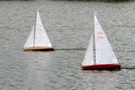
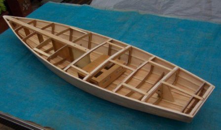
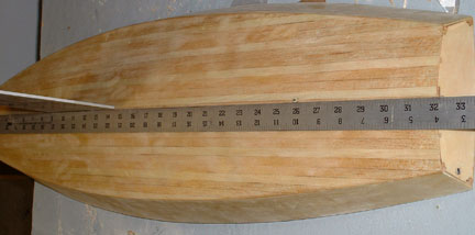
The Star45 is a 45" long hard chine hull; semi-scale model of the full-size Olympic Star. This model is recognized by the American Model Yachting Association, AMYA. S45's weigh 12 pounds (minimum), have 12 inch beam. They are easy to scratch build and sail. Well suited for building by by the novice builder and skippers looking for a classic looking model to race.
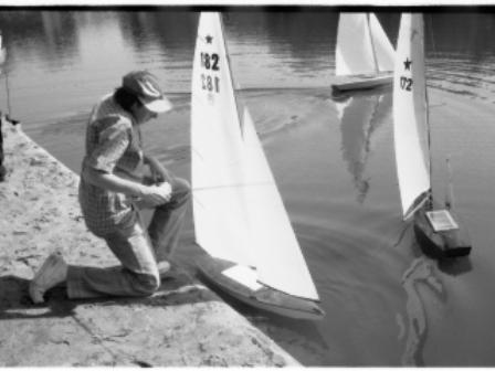
The Star 45 is a terrific boat for sport sailing and family fun. If you want to race other Star 45's in AMYA regatas you meet the AMYA Class specification.
You will find that much of the the information included in this article also appears in posts found on my blogs: "The Star 45 R/C Model Sail Boat - Builders Journal", "Model Sail Boat Building, How To Build A Wooden Star45 R/C Sailing Model" and contributions of members of the Star45 Class Yahoo Group.
The modern R/C model sailing craft is as different from a toy boat as a museum display model is from a child's tinker-toy creation. A model sailing craft operates with the same sophistication of design as any full-sized yacht. As a skipper you control all the sails and the rudder. This model is wind powered. It is not intended to be powered by a motor.
The information presented here is a basic start to finish, building of a wooden sailing model .
For builders wanting to cover their model with fiberglass A separate article will offer directions for covering a wooden star with fiberglass.
With the popularity of radio-controlled models, the number of people interested in owning a model yacht has also grown - in geometric range. As with model aircraft, the choice of sailing models runs the gamut from child's toy to sophisticated craft.
Over the past 40 years I have fielded many questions regarding the choices and considerations which go into selecting a radio-controlled sailboat.
Four questions are asked over and over by prospective skippers: How do the radio-controls work? How much do they cost? What do I look for when I buy mine?
These questions are addressed in How to select Your Radio-Controlled Sailing Model By Dave Mainwaring
The
Star 45 Through Time
A
Brief History of the
Star 45 Model Yacht
Compiled, from information
provided by enthusiasts in the building and sailing of Star 45s,
by Phil Geren, 23 June 2006 Edited by Dave Mainwaring March 2008 Early Years
Early
Boat Design and Production
The Beginning
The International Star Class racing yacht, mother of the
Star 45 model yacht, was designed and first built in the winter of 1910-1911.
It is an open cockpit, fin-keel sloop, having an overall length of 22.8 feet.
It has a fast, high aspect ratio hull, incorporating a compound curve in the
bottom, with a skeg forward of the rudder. It carries a big-footed mainsail and
lots of canvas. Roughly more than 9,000 full-size Stars have been built.
In the early 1960s Jay Brandon, proprietor of Dumas
Products, Tuscon, AZ, designed and built a scale model of the International
Star based on the 1945 edition of the International Star Class Yacht Racing
Association’s (ISCYRA’s) official plans, at 1/6 scale, or 2 inches on the model
being equivalent to 12 inches on the full-scale boat. At that scale, the model
was roughly 45.6 inches long, and, voila!
the Star 45 model yacht was born.
The model was originally designed for free-sailing, not
radio control. However, lightweight, World War II surplus, low-voltage,
electric servo mechanisms eventually became plentifully available. Those servos,
adaptable to radio control in sailboat models, were the first to be available
economically, and they were instrumental in the phenomenal early growth which
took place in the Star 45 model yacht fleet.
Early Jibsails were loose-footed and overlapped the Main so that individual mechanisms were required for
control of the Mainsail and Jibsail sheets. Elaborate worm gears were used to
pull the sheets. To accommodate these bulky mechanisms, Jay raised the model
yacht’s freeboard by three quarters of an inch (which would have been
equivalent to almost 5 inches on the full-size boat!) The worm gears were two
threaded rods which ran longitudinally under the deck, each driven by a Pittman
motor. “Travelers” moved forward and aft on the threaded rods and pulled or
loosed the sheets. Wet nickel-cadmium batteries provided power.
In the July 1966 edition of Radio Control Modeler Magazine,
Dumas Boats advertised a Star kit: “New
from Dumas Boats, 45” radio-controlled Star Class Sailboat. All the thrills and
skills of sailing big boats! 1/8” birch plywood hull with die-cut frames,
mahogany deck, 64” high mast, ready made sails, instructions for building boat,
sailing boat, installing RC equipment, and forms for making your own ballast. A
Star Sailboat for racing – slightly modified for R.C. $45.00. The “hot ones”
designed for “go” … ideal for show.”
The first Star 45 to be registered
with the AMYA, sail number 1, was reported
in the second issue of Model Yachting (Winter ’70-’71). Rod Carr.)
The Dumas hull’s bottom was made of two pieces of one-eighth
inch thick plywood, without the compound curve present in the full-size Star.
The hull and controlls weighed about fourteen pounds. Don Prough would later
license Dumas Products to produce the smaller “Probar” arm winch, however the
increased freeboard was maintained in the Dumas design. Three thousand wood
kits were sold between 1966 and 1995.
More
Designers/Builders Join In
Other talented designers and builders of models began
working in parallel with Dumas. Beginning with the Dumas design, the early
practice was to cut the high freeboard down, to cause the hull to more closely
resemble the appearance of the International Star, and to lighten the hull.
This had the effect of shortening the hull’s overall length.
The beam of the hull varied from builder to builder. Sails
in the early days mainly came from Rod Carr’s model racing sail loft in
Springfield, VA. Dave Mainwaring, in Needham, Mass., used an old, abandoned
street sign for the material to fashion a keel of a design he found pleasing,
being significantly narrower than the Dumas original and having a slight
aftward rake, from top to bottom, in the aft edge (the Dumas keel’s aft edge
was vertical.) Dave also designed a semi-balanced spade rudder, abandoning the
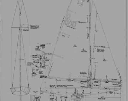
International Star’s skeg. Dave drew sketches for his Star 45 design, having
lines scaled from the 1946 edition and then from the 1976 revision of the
ISCYRA’s official plans. Dave’s friend Jack Sullivan, a design draftsman,
rendered the sketches on mylar, and both Dave’s and Dumas’ keel designs were
shown. These drawings have undergone three revisions. Revision 3, the current
official version which governs the dimensions of Star 45 boats built from
scratch, signed by John W. Mayers, clearly shows the profiles of the Mainwaring
and Dumas keels.
The idea of using fiberglass reinforced plastic for hull
construction was inside many a cranium by the mid 1970s. In January of 1976
Dave Mainwaring borrowed a wooden hull from Dave Holmes and made what is
probably the first female mold for making fiberglass Star 45 hulls. By July
1976 Dave had advertised for sale his “Sirius 45, Star 45 Class model radio
control sailboat” – the short kit consisted of fiberglass hull, fiberglass
deck, fiberglass aerodynamic keel shells, sail plan, construction drawing, and
model builders guide, all for $65.00.
Sure enough, the rumor was true, and in 1976 Dumas also
began making its hull design in fiberglass. The Mainwaring mold was then passed
to John Reynolds in Orlando, FL, and John made many fiberglass hulls. His wife
Mary became a highly-reputed maker of precision-built Star 45 sails.
Jerre Maxson, a tank mechanic during the Korean War with
prodigious mechanical skills, built 27 wooden Star 45 hulls for others. He also
built the fiberglass mold which was eventually passed to Skid-Do Industries,
Clayton, Ohio, and was used to make 50 hulls by 1995.
In 1978 the Mainwaring/Sullivan drawing was approved by the
AMYA as conforming to the Star 45 official specifications, during Bill Weiss’
tenure as Class Secretary. That legalized all the hulls manufactured by John
Reynolds.
In 1982 the AMYA membership approved Dave Mainwarings
recommendations to legalize all pre-existing Star 45 model yachts and to reduce
the minimum weight from 14 pounds to 12 pounds.
By 1984 deck designs were standardized with a straight king
plank, resulting in a straight line from stem to stern along the longitudinal
centerline of the deck. This reduced sheer and made it possible to make the
deck from one piece of wood or
fiberglass. John Mayers made such a plug, based upon 1/6 scale, from the 1976
ISCYRA plans and sent it to Ray Ozmun of Ozmun Products for use in making a
hull mold. Ozmun made many hulls for new enthusiasts.
The Rest of the Early
Design/Production Story
This writing is incomplete in many respects, but most
importantly due to the lack of information about the designs and leadership of
others such as Bob Blackwell, Ray Ozmun, and Paul Galloway. Many Blackwell,
Ozmun, and Skid-Do hulls are competing valiantly and winning races. Time was
not available to obtain this information, however, as this is a work in
progress, information will be sought. Also needed is information about
sailmakers and rig design, for a later article.
Readers, please bear with me as I continue to put flesh on
the bones of this initial effort.
Your contributions of information would be welcome and
highly appreciated. Please write to me at philgeren@aol.com,
or Phil Geren, 1044 Chimney Rock Road, Houston, TX 77056, and share your
invaluable experiences and memories about these missing pieces, especially for
the period from 1966 to 1995.
The Pioneers and the Rapid
Early Growth of the Star 45 Class
From preceding sections, you are familiar with the names Jay
Brandon, Don Prough, Dave Mainwaring, Jack Sullivan, John Mayers, Dave Holmes,
John and Mary Reynolds, Jerre Maxson, and Rod Carr and of their many contributions
to the development of the Star 45 Class Model Yacht. Now, let’s look at other
important pioneers and at how the Class has developed over the years.
In the period from 1970, when Star 45 Number 001 was
registered, to 1981, the rate of growth in registrations of Star 45 model
yachts averaged 18 boats per year. That is a hefty growth rate, especially when
compared to the average since 1981, which shows a decline, in other words
attrition exceeded new registrations by almost 4 boats/year. One of the
objectives driving the writing of this Newsletter is to get the Star 45 Class
growing again. Notice that these data are for registered boats, not active
skippers, which is a much harder statistic to derive.
Rod Carr, sailmaker, builder, and champion sailor has
chronicled the scene from 1970 to 1978, and the following paragraphs are
excerpted from his writings.
“Early policy decisions of the AMYA Board guided the
skippers of radio controlled yachts to register their boats with the organization
and to have written class Rules and a class secretary, as requirements for
establishing a class of boats for AMYA sanction. At least 20 registered boats
are required for AMYA sanction of a class.
“In winter of 1970-71, the AMYA President designated Ralph
Newman of Clarence, NY to head up the effort for the Star 45. By spring 1971, the position was transferred
to H. Whitney (Pete) Cutler of Brookside, NJ.
“Model Yachting Magazine Issue #5 (Fall 1971) featured the
first technical contribution in an article titled “Improving the Dumas Star 45”
authored by Ben Hogensen. Ben suggested
improving maneuverability of the boat by enlarging the rudder, or even removing
the skeg and providing a balanced rudder like found on the Vortex Model
Engineering Santa Barbara and Soling 50. He advocated a stern-down longitudinal hull trim to counteract the
tendency of the bow to be pressed down when driven hard to weather, and finally
suggested the simultaneous sheeting of main and jib, eliminating the heavy and
slow independent sheeting provided by the original worm-gear Dumas winch.
“The Stars had risen to 12 boats registered, and Francis
Smith, Prospect Park, PA and proprietor of a hobby shop was designated the
first class secretary, though the 20 boat minimum had yet to be reached.
“From AMYA Model Yachting #7 (Spring 1972) throughMYA Model Yachting #17 (Winter 1974) the
class underwent fairly consistent growth with the 20 boat minimum reported as
being reached in Fall of 1972, and class size varying between 15 and 33 boats
until Fall of 1974.During this period
there was one event held by the Mid-Ohio Stormbirds in which a Star 45 was
reported as sailed.No other events for
Star boats were announced in Model Yachting, and no Class Column appeared in
Model Yachting, which undoubtedly contributed to the lack of organized
competition, and the lackadaisical growth pattern over the period.”
In Model Yachting #18 (Winter 1974), AMYA’s Bob Harris
appointed Rod Carr as Class Secretary, and Rod immediately scheduled the first
Divisional Class Championship Regatta (DCCR) and first Annual Class
Championship Regatta (ACCR) for the 1975 sailing season. Star 45 Column also began to appear
regularly in Model Yachting.
“Model Yachting #19 (Spring 1975) reported 24 Star 45’s registered
with the class, and announced the formation of a Class Technical Committee, the
first class technical committee in AMYA, with membership of:
James Frye, Oregon, Ohio
Dave Holmes, Pleasantville, NY, future Star 45 Class Secretary
Tom Johnson, Savannah, GA
Jay Brandon, Tucson, AZ.
“With momentum building, Dave Holmes was nominated for Class
Secretary, as it was deemed important that the class have an opportunity to
vote for its chief officer, all others having been appointed by AMYA
management.
“By the summer of 1975, the emphasis placed on class
publicity was beginning to pay off.The
Eastern Divisional Championship was held in Savannah and reported in Model
Yachting.This was quickly followed by
the report in Model Yachting #21 (Fall 1975) of a total registered class
population of 37 boats.The Star
definitely lagged other classes such as the EC-12 and Santa Barbara, which had
been carrying on aggressive publicity and were each approaching an active class
boat population of 150.
“The 1975 ACCR was competed for by a 7 boat fleet in
Springfield, Virginia.
“Class population had grown to 44 boats by spring of 1975,
and the 1976 ACCR was scheduled for July 18, 1976 at Lake Alcyon, Pitman, New
Jersey, under the stewardship of the TriState Model Yacht Club.everal Star 45 events were held at the site
over the next few years, and eyebrows were certainly raised when it was
discovered that the lake and associated park were built over a landfill that
was ultimately designated as a Superfund hazardous waste site requiring major
and expensive environmental restoration.
“After his year as Class Secretary, David Holmes turned the
reins over to Al Hemmalin of Middletown, RI. By fall of 1976 Model Yachting #25 reported 66 Stars registered, and a
successful completion of the 1976 ACCR at Lake Alcyon.he fleet was made up of returning skippers
as well as new skippers who were drawn to the rapid growth of the class.”/p>
To continue the encouragement of new skippers, Rod Carr
donated an engraved, spun aluminum dog dish trophy entitled “Spot’s Dish”,
named for Rod’s Star 45 which had won the first three Annual Class Championship
Regattas.
“By the end of 1977 AMYA had ceased publishing Class
Population statistics, partly because the manual record system made it
difficult, and partly because some thought that showing small class numbers
somehow would reflect poorly on classes that weren’t growing.hether true or not, the practice makes it
difficult to follow the growth of the class in the pages of Model Yachting and
it is not until Model Yachting #31 (Spring 1978) that Class Secretary Bill
Weiss reports that the 143rd Star was registered.
“Published class records are sketchy until Model Yachting
#41 (Fall 1980) reports a 9 boat ACCR won by Bill Rader who was to become Class
Secretary a year later.In Model
Yachting #44 (Fall 1981)the Class
Secretary reported that 200 StarS had been registered since 1970, but the number
of current active skippers on the AMYA roles was not given.“
Readers are encouraged to write to Phil at philgeren@aol.com with information which
should be included in this writing to make it as complete and informative as
possible.
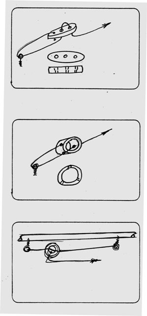
From Rod Carr:
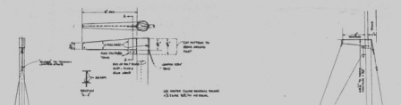
{Spot}“The hull was made of 3/32” aircraft ply over 1/8” frames
copied from Dumas kit parts with the ¾” of extra freeboard removed (Figure 1 at
the end of this Newsletter).A balanced
Vortex aluminum rudder was fitted as was the fiberglass keel and bulb from a
Model Masters Yankee 50/800 model. Molten lead was poured down the fin into the bulb, and the fin length
adjusted to match the draft of the kit boat. Decking was 1/16” aircraft plywood with a very large hatch.
“The
standing rigging was typical EC-12 configuration with one set of spreaders,
jumpers, and upper and lower shrouds.No
topping lift was fitted.Early testing
showed that boat balance could be well controlled by mainsail set and trim, so
a single mounting hole for the pegged-base mast was provided in the deck.he mast sat upon an aluminum plate which
provided the bottom mounting point for the mainsail boom vang.his arrangement coupled with loose standing
rigging tensions in light air, encouraged the mast to rotate a bit on each tack
giving some aerodynamic advantage over a fixed arrangement.he masthead crane was extended substantially
to allow the backstay to clear the mainsail roach.
“Running rigging consisted of a mainsheet which began on a
cleat on the boat transom just to port of the “S” in Spot. It went forward to a
double purchase blocking system on the single arm Harris L’il Herc bang-bang
winch, and then out the sheet exit guide aft of the mast step to the main boom
and down to a manually adjusted travelerThe traveler was a curved piece of curtain track with a well greased
plastic slide as a traveler car.This
item was well worth the effort in construction and adjustment as it provided
the control necessary to keep mainsail twist under very fine control from the
transmitter, even though proportional servo response was yet to become
common.If the skipper kept his wits
about him, it was rare for the boat to fail to be first at the weather mark.
“Sails were of 2 oz dacron, and featured what was termed
California Cut in honor of some early experiments carried out in the Golden
State where broadseams were placed in the luff area of the sails extending back
only about half way to the leech.The
result was a quite nicely cambered sail that had a smooth leech.he result was quite remarkable acceleration
which paid off, given the relatively low displacement of the hull.
“With
no Star fleet nearby, Spot was sailed as much as possible with the Potomac MYC
EC-12 fleet.She held her own in light
air as having essentially the same sail area and less wetted surface she
generally did well, out-accelerating the heavier full-keeled boats.ut in medium to heavy air she really came
into her own.Pressed to weather, the
leeward bow of the hull did a good job of encouraging the boat to round up, and
she routinely out pointed the 12s, much to the dismay of the locals.er hydrodynamically shaped keel fin assisted
in windward performance, especially when facing kit boats that were using the
flat plate fin. Her downwind
performance in light air was not sparkling, but if trimmed bow up, she was
quite a sight in heavier air, almost planing in gusts.o doubt that the experience gained in racing
in the competitive EC-12 Fleet was a strong contributor to the boat’s success
in ’75 – ’76 – ’77.
“The boat’s configuration was retained without changes
except for a repainting from the original blue topsides and white bottom in
1975 to an all yellow hull, keel, rudder for the ’76 and ’77 season.eclining winning margins showed that, as a
benchmark, she was being rapidly overtaken by the developing construction and
sailing skills of the rest of the class. So she was gracefully retired after her third win.
A history of model yachtingby
Norman
Hatfield is available on line. "The I.M.Y.R.U., particularly by its then Chairman, Norman Hatfield, to get Model Yachting accepted into membership of the full-size governing body, the International Yacht Racing Union (IYRU). This work culminated on 1st May, 1990 when the I.M.Y.R.U. became the Model Yacht Racing Division of the IYRU (IYRU- MYRD). In its turn, in August, 1996, the IYRU changed its name to the International Sailing Federation (ISAF) and MYRD is now the Radio Sailing Division (RSD)."
This is a compellation of articles; " "Model Sail Boat Building, Making A Wooden Star45 R/C Sailing Model", "The Star 45 R/C Model Sail Boat - Builders Journal", and "How to select Your Radio-Controlled Sailing Model". John Fisher, Phil Geren, and many members of the Star 45 Yahoo discussion group provided essential content.
Thirty years ago started to write a, step by step, manual of sorts to assist modelbuilders that want to build a radio controlled ship models.
The manuscript sits in my files. My blogs and my web site are also works inprogvress. Changes seem to take place every ten years more of less. I sailed my first model tethered by a string off the floats at the Wollaston Yacht Club, Quincy, MA, as a pre-teen sometime in 1947. It broke away and was seen sailing off towards Rainsford Island a 21 acre island situated between Long Island and Peddocks Island. I got introduced to the International Star Class while crewing on one in 1954 out of Quincy Yacht Club. Thirteen years later in 1976 I scratch built my first model Star45.
In 2006 John Fisher drew up the lines of the Star45 model as CAD (computer aided design) files. He arranged for Steven's Aero to lazer cut the frames (aka bulkheads) and the building of S45's was revolutionized and the class gained world wide attention of modelers wanting to build a wooden sailing model. The CAD files are available for downloaded from www.mainzone.com and so you may have them lazer cut yourself.
The modern R/C model sailing craft is as different from a toy boat as a museum display model is from a child's tinker-toy creation. A model sailing craft operates with the same sophistication of design as any full-sized yacht
Over the past 30 years I have fielded many questions regarding the choices and considerations which go into selecting a radio-controlled sailboat.
Four questions are asked over and over by prospective skippers: How do the radio-controls work? How much do they cost? What do I look for when I buy mine? And, where can I get plans and instructions for building a sailing model? I've addressed these questions in "How to select Your Radio-Controlled Sailing Model" published on my MainZone Publishing blog.
In 2006 Phil Geren's "Brief History of the Star 45 Model Yacht"
based information provided by enthusiasts in the building and sailing of Star 45s .
The AMYA STAR 45 Class discussion group is a terrific place to exchange ideas and talk about building Star 45 models for racing in AMYA regattas.
Feel free to contact me, Dave Mainwaring mainwaring @ rcn.com
Lists and more lists. Things to do, things to get.
Join the Star45 discussion forum.
- Order Star 45 construction drawing from AMYA store.
Or download line drawings from a web site.
- Buy or borrow books on wooden boat building.
- You can build the model in units to be assembled as a finished model.
- It is safe to say most builders start the hull first.
- Decide on type of planking and wood to be used to build the model.
- Decide on which glue to use and purchase.
- Set aside a work space for building.
- Review the bill of materials need to build the model and buy the materials.
- Order deck hardware and mast fittings.
- Order mast (if you are buying a mast)
- order sails (or sail material).
- Select a radio system.
- buy a sail control unit (winch)
- Decide if you will make a keel bulb or if you will buy a keel bulb.
While the hull is under construction:
- Build cradle to hold boat under construction and when finished.
- Rudder assembly
- ( mast and booms)
- test out Radio System and sail control unit
After hull is planked and before decking:
- Determine how you will attach the keel fin to the hull.
- Keel fin and ballast bulb
- Install keel trunk or make provisions for mounting keel.
- Install radio and sail control unit, Then remove while construction continues.
- Construct deck and hatches
- Test access to equipment located inside the hull.
- Provide a exit guides for sheets.
- Provide a exit guide for radio antenna so it can be attached to mast or stays.
- Check wiring and install power switch for turning off batteries
- Install/mount deck and fittings
-
Test mount keel fin
- If necessary Paint hull, rudder and keel
- Assemble hull, rudder and keel
- Set up mast and boom.
- Install radio controls.
- Check running rigging.
-
Attach Sails
dry sail model
-
Find pond and Sail
,
- Find place to Display model,
- Clean up model, dry the interior, charge batteries, place in safe Storage
.
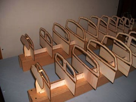
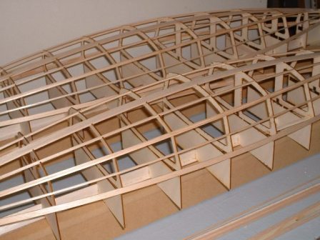
The new generation of wooden S45's began in 2006 when John Fisher drew up CAD files for laser cutting frames and building jigs. When Dumas offered the first kitted wooden Star45 ( circa 1966 ) it had 1/8” birch plywood hull with die-cut frames. Dumas sold thousands yet only a few got registered with AMYA.
John's frames are scaled from the lines of International Star Boat, John's 2006 hull's weighed in at one pound, far less than the original Dumas boats. John Fisher built two models and provided me with photographs as the model construction progressed along with comments and pictures posted to the Yahoo Star45 group. In the following years laser cut frames have revolutionized the construction of the S45 models. John has continued to improve his building techniques and the laser DXF files along with an ongoing stream of construction photographs. These were posted blogs and mainzone.com making them available world wide. Thousands have examined the posts and many have built new Star45's.
g Start by obtaining laser cut frames.
Step one Assemble a Building board
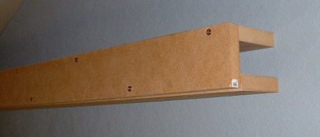 Start with a 3" wide 3/4" MDF board that true and straight.
Assemble the stern section.
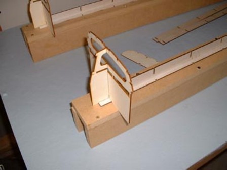
The vertical parts are installed once the stern section is assembled. These parts keep the shadows/frames square and vertical.
With the building set up the next step is to lineup all the frames (if they are solid pieces they are bulkheads).
A word or two about glues. Model boats are held together by glues and adhesives. Unlike other models boats get wet. The glued joints may bet wet occasionally or they may get wet for long periods of time. Model sail boats do get water inside. While the outside dries off quickly the interior may stay wet if the skipper doesn't take steps to get the inside dried out. During a long regatta the insides may stay wet. The hobby glue used for years on other models may weaken or part ruining the boat so choosing a glue or adhesive is an important decision.
Another consideration is creep. Some waterproof glues allow parts to move, sometimes after several years. How important an issue this is depends on how long you want the model to last. I have models that I built thirty years ago and will still be sailing fifty years more. Having had keel fins delaminate within a year or two because of improper gluing I recommend using a very waterproof glue. Do not use a glue unless you know it is waterproof or at a minimum water resistant.
To cover with fiberglass or not to cover. Glassing adds a level of complexity. It also requires added materials and adds weight to the hull. A good alternative is buying a bare fiberglass hull instead of scratch building the hull. However glass hulls will never equal the beauty of wood, imho.
Building is not a linear process. Some builders jump right into hull building. Others will assemble all the needed materials then start building. We'll start with the hull and at the same time build other parts that will be as assembled as a finished model.
Early on decide what wood you will use for building the model. The hull can be a single type of wood or the bottom, sides and deck can each be a different wood.
Before ordering laser cut frames, decide on the wood for the hull sides if you want to meet the AMYA specifications (when planked the beam may not exceed 12 inches). John Fisher has been very cooperative in adjusting the drawings to accommodate builders needs.
The wood you use may be determined by availability. My own preference is 1/16 aircraft grade plywood. Others use balsa, cedar etc.
Looking on the web it appears most 1/16 ply is three ply birch. A big issue is finding plywood long enough for sides. I used to buy 1/16 ply from Violete Plywood in Lunenberg, MA. He imported thin ply for the furniture industry and the sheets were 50 inches by 50 inches. 48 inch lengths will need to be splices to get the needed length. Aircraft suppliers also offer thin basswood plywood (basswood being the hard core from the balsa tree). Violete simply rolled up the plywood, wrapped it in brown shipping paper and sent it to me.
Paul k, Johnson, model airplane builder, has an tutorial on making your own plywood. I think you could make a 6" x 5'MDF jig and vacuum bag home-brew plywood. One gadget I have in my shop is a homemade drum type thickness sander. I can sand paper thin planks from most any wood. There are suppliers that sell veneer that is paper thin that could be used for beautiful ply.
Balsa is light and easy to work with. However it is not particularly strong if the model gets hit it can be punctured. Most builders cover balsa with fiberglass. See the wooden model building blog for fiberglassing information.
Keep in mind that full sized Stars are planked. You won't lose your amateur standing if you plank your model
Billie Geisler's commented on August 1, 2006 in a post to the Star45 forum that he builds hulls from cedar rather than balsa. He selects clear, straight grained cedar fence pickets. He cuts the rough edges and flats off with a 10 inch table saw, then use a 3 inch table saw from Micro- mark to cut the final planks.
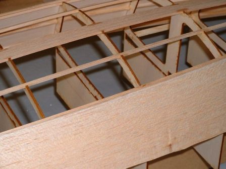
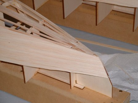
Look at this frame: Note that the deck rails are made of two pieces.
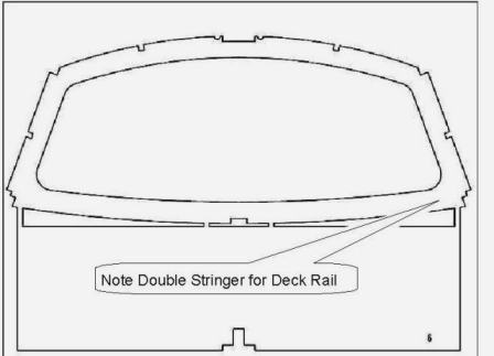 1/4X1/8 for the first one and then 3/8X1/8 for the second. Begin at the transom with the rails and stringers. Start one side and go forward to station 9 or 10, then do the same on the other side. Then go all the way to the front with one side. Starting both sides at the same time keep the transom from twisting.
The 1/8X3/8 spruce for the chain plates. This needs to be installed before the rails go in.
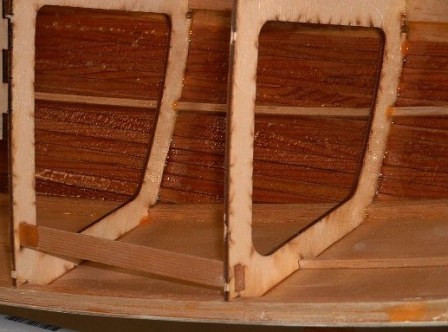
Photo showing the two balsa keelson pieces going in these are 3/8 by 1/8 (you can use spruce instead}.
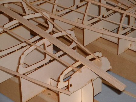
When the rails and stringers installed, you are ready for planking.
When the rails and stringers installed, you are ready for planking.
Photo showing adding the side planking
You will probably want to trace the outline onto the wood and cut close to shape before gluing it on.
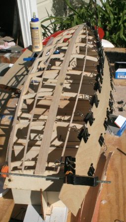
Photo showing side plank after being glued on. Make sure it is located correctly before starting gluing.
Photo showing the planks after being trimmed close to the stringers.
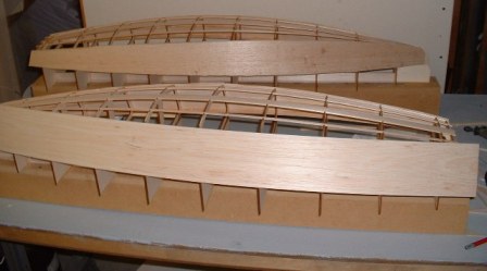
Use a # 11 Exacto to trim the balsa planks.
Go slow and take multiple passes here. You don't want to remove too much material or you will get a gap when the bottom is planked. Also trim the rails close at this point.
Use a sanding block and sand the sides to match the bottom curve.
Balsa sands really easy so this is pretty quick. Use 220 grit paper
When the sides match the bottom curve and they are ready for bottom planking.
Bow sections after sanding and ready for bottom planking.
http://groups.yahoo.com/group/Star45/ for discussions with other Star 45 sailors.
http://groups.yahoo.com/group/Star45/ for discussions with other Star 45 sailors.
Bow sections after sanding and ready for bottom planking.
r groups.yahoo.com/group/Star45/
http://groups.yahoo.com/group/Star45/ for discussions with other Star 45 sailors.
The keel on the wooden S45 model is the fin and bulb type. The fin may be solid or hollow and constructed of reinforced plastic, plastic laminates, fiberglass, wood or metal. The strength and rigidity of these keels is paramount. The keel fin may be bolted onto the hull or go up inside the hull to be held i place by a keel trunk.
The Star models can sail fast and bounce along the waves. With a heavy keel bulb hanging a the bottom of the keel you don't want the keel twisting and distorting as the model heels and changes position. It is also important that you support the keel mounting within the hull. The exact keel mounting system will be determined by your choice of fin materials. Racing models will pay attention to the foil shape of the keel. However, flat sided fins work fine for sport sailing. The "Mainwaring keel and bulb" is a result of trail and error.
The important ingredient is building a model where the Center of Effort and the Center of Lateral Resistance are lined up. The Mainwaring keel and ballast bulb concentrates the weight, other long symmetrical bulbs may spread the ballast weight over 9 inches.
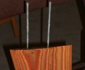
Flat metal plate keels are easy to make if you have access to a metal band saw. Print the fin profile Add material for inside the hull and inside the bulb. Glue that to a sheet of 3/32 aluminum with 3M77 spay adhesive and cut it to shape.
Another method to make a fin is to cut the shape in two pieces of 1/16 ply, then tape the edges together. Insert a couple of long threaded rods parallel between the two sheets they create an airfoil and extend from the top for attachment. Then fill cavity with epoxy microballoons mix. Using this method you could also glass the outside for additional stiffness.
You could also layer sheets of plywood and laminate sized pieces to achieve a airfoil shape. Each layer should be smaller than the last and then sand to blend the layers. John Fisher and Stevens Aero offer lazer cut wood to laminate keel fins.
The ballast bulb for the this model may be constructed of any material {ballast materials denser than lead is prohibited}. Note that the actual bulb shape is left to the builder's discretion, but will not exceed 9.75 (9 3/4) inches from the front of the keel bulb to the rearmost point of the keel or bulb. There are suppliers of ballast bulbs. Check their bulb shapes, weight, length and weight.
There are a variety of bulb shapes, there are even winged keels.
Wikipedia describes winged keel is a sailboat keel, usually of high aspect ratio, that uses a nearly horizontal foil, the "wing", at the bottom to provide additional performance. The horizontal foil serves two purposes: it acts as an winglet on the foil, effectively doubling the aspect ratio, and they produce additional lift, but downwards. Because the yacht is heeled over when sailing upwind the leeward foil is closer to vertical, and provides additional side force hence making the boat sail upwind more efficiently. The windward winglet is closer to horizontal and hence produces a force directly downward, which gives a small benefit to the vessel's stability. Winged keels are generally found on high performance sailboats, if they are not prohibited by class rules. They are only of benefit for yachts sailing upwind where stability and the ability to produce side force are important. Downwind the extra skin friction drag is a hindrance.
The keel fins and ballast bulbs may be removable and interchangeable.
If you race the model in AMYA regatta they may not be changed, interchanged, substituted or otherwise manipulated once any heat or series of heats in which scores will be compiled, has started. Mechanically movable keels or ballast bulbs are specifically prohibited from use in AMYA Star 45 Class Yachts
Ballast bulbs may be made from any readily available material, such as poured lead, lead shot, etc. (Note: When using material such as lead shot, the mass must be solidified through the use of a bonding agent such as fiberglass or epoxy resin, paraffin wax, plaster-of-paris, poured over and through in order to create a solid mass.
Hull internal ballasting: Added ballast-weight may be placed within the hull. Ballast as is anything carried aboard the model for the main purpose of changing the weight distribution of the model and/or weight of the model. The AMYA s45 class specifies such ballast shall be fixed in place by gluing, fiberglassing, or bolting (bolts and screws.
Important to note that he Star 45 Class specifically excludes radio equipment, sail controls and batteries (power cells) from being considered ballast. The use of Velcro or similar quick release fasteners is prohibited as methods of mounting ballast. However batteries (power cells) which are not ballast can be mounted with Velcro allowing them to be placed within the hull to change the weight distribution. A battery pack can be made up of AAA,AA, C, D and gel cells. Their placement with the hull can trim the hull's weight distribution. When deciding on the hatches for your model keep in mind access not only to radio and servos but also access to battery mounting locations.
How to make your own keel bulb is an open item. Jim Adams wrote that he make a plug from balsa and finished it to a smooth finish.
Then, using two aluminum pans (the kind that you throw away). He fills the first one with plaster. Having heavily waxed the balsa-bulb immerses it in the plaster half way to the bulb center line. Using two pins through the center to hold it down he lets the plaster harden. Then he pulls out the balsa-plug covers the mold with (plastic) Saran wrap over places the waxed balsa-plug back in the mold.
Now comes the fun part. You may need to use rubber bands to hold the plug in place. Fill the second pan with plaster and lay the original plaster mold on top of the second plaster filled pan. It is kind of messy but it works. When the second half hardens (about two hours) pull them apart. You will need to plug any holes. Cut in a spur (looks like a funnel) big enough to pour in the lead). Create small air vents on the side that is on the same side/end the pour hole the mold. Air must vent when the mold is filled. Pouring molten lead is dangerous. The plaster mold which Jim Describes must be absolutely dry and free of moisture or the lead can spray out of the spur. The hot lead hitting a cold mold can splash back. Wear safety glasses and gloves, and body coverings.
You may want to place a piece of wood simulating the keel fin into the mold so you can attach the bulb to the fin. You may also want to consider using a two piece mold large enough to hold a lead pellet-resin mix ballast material and them epoxy or bolt the halves together. Consider making the bulb oversized until you are certain it weighs enough. {I weigh a finished hull. Place it in a bath tub. Weight the model to float at the water line desired. The weigh it to see how heavy the keel needs to be.}
Keel Tubes installation --photographs by-- John Fisher
While we are working on a bare hull we must decide on the keel fin and how it will be mounted (attached) to the hull. Keep in mind how you will access the keel mount when you design the hatches on your deck. If you decide to have a removable keel don't cover up the keel mounting system.
Review the basic keel fins.
Bolt mounted fins:
keel using a keel trunk:
Making a keel-trunk is simple. The top of the trunk should be above the water line. It is simply a wooden box built over the end of the keel stub that extends into the hull. It can be wood (plywood, etc.) The length is determined by the stub dimensions. If the keel will be removable make certain the stub doesn't get keyed in and can't be removed from bellow the hull. It is easy to prop the fin and trunk down into the hull from above and discover it can't be removed from the bottom when the deck is in place. Here are pictures from one of my old hulls. I use auto-body resin paste to attach the trunk to the hull.
Using to 3/6 by 1/2 inch SS bolts allow the bolts to be removed and an alternate keel installed. There is a lot of equipment inside the hull so easy access to the nuts and bolts is required. I wire the bolt heads together and can easily remove the nuts, push the bolts out of the way and remove the keel.
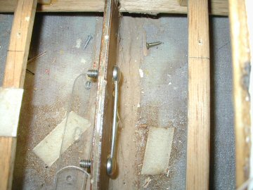
Installing Keel Mounting Systems
These photographs show keel tubes and tubes glued in a hull. John Fisher uses brass tubes and reports that they were very easy to align due to the snug fit in the drilled holes.
The keel fin selected had standard bolts for mounting to the hull.
He then took an aluminum rod and thread the end to hold the keel.
The tubes were glued into the hull using JB weld since it has very good strength for bonding metal ( JB weld is the silver colored epoxy). Note: Time will tell if it was a good choice.
No matter which mounting you select. Make certain when the mounting is installed the keel is centered bow-to-sern and vertical!
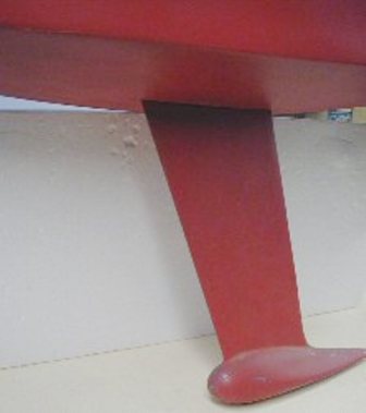
The AMYA Star class doesn't define the rudder shape persay. However within the specs is a note that scratch builders should build to the official plans:) "The Star 45 Class establishes " " New molds, plugs and scratch built models shall conform to the approved plans and specifications." The plans show the rudder and Keel the Jack Sullivan and I designed back in 1976.
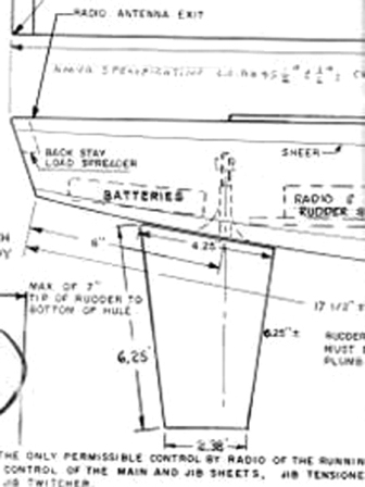
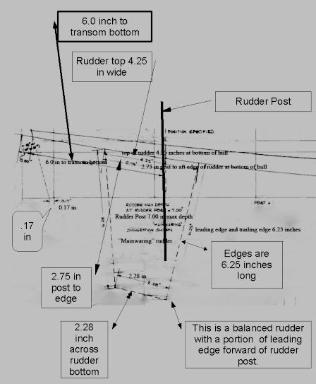
AMYA Star 45 Class Rules, 2008 "Rudders may be constructed of wood, fiberglass, plastic, plastic laminates or metal. The exact shape is not specified, but they may not exceed 4 1/2 inches at the hull (fore and aft) 3 inches at the bottom, (fore and aft); and may not project more than 7 inches below the hull when measured at the post." If your building your wooden start and referencing this article my recommendation is to stay with the balanced rudder shown on the drawings.
Here are two drawings of my rudder design. The left hand drawing show the rudder of a molded fiberglass hull and the righthand drawing is based on the 2008 AMYA star plans. The balanced rudder lakes some of the load off the steering servo The leading edge portion is pressured by the water flow as the model sails. Interesting aside. If the steering servo can turn the tiller hard over to 90-degree to the center line the rudder can act as a brake and stop forward motion:) s45_dlm_rudder_05.jpg
One way to build a rudder quickly and easily is cut out the shape in a thin material, tape the sides together, insert the rudder shaft, fill the inside of the rudder with epoxy. This takes about 10 min or so to do.
While the hull is being built it is time to line up deck fittings and spars.
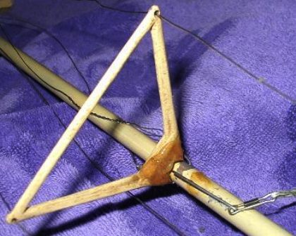
A simple and light weight plywood strut made from scrap 1/32 or 1/16 ply.
Main Booms, Goosenecks, and Vangs,
u mast
p>Decide on the mast you will use. Our masts shall be made of wood or aluminum. {Swing rigs, rotating and permanently bent masts are prohibited." "Masts shall not exceed 3/4 inches square when measured at the thickest point of the mast. Maximum mast height shall be 70" when measured from the deck, inclusive of the crane. Rotating wind indicators and burgee staffs are not included provided the backstay is not attached to them in
order to circumvent the 70" maximum mast height specification."
Wooden masts have been around for years. Light weight straight grained spruce can be hard to find. Two lengths of 3/4 by 3/8 spruce with strip of 1/32 aircraft play between them makes for a solid mast. Compared to light weight extruded aluminum model masts, wood is a distant second choice.
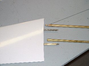
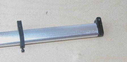
Extruded Aluminum Spars
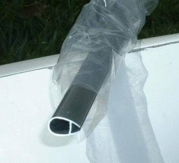
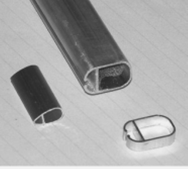
photo's courtesy of "Larry Ludwig" at www.LudwigRCYachts.com, Ludwig Mfg.
v mast
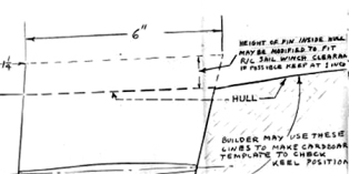
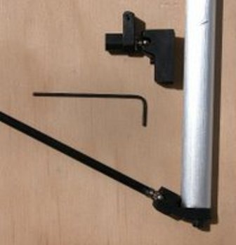
Model masts are self supporting and stepped on deck. This allows the skipper to position the mast when balancing the model for sailing. Mast steps come in many styles. A common one is simply a short pin in the foot of the mast that sets into a mast step with series of holes.
A mast jack is a variation of the mast mounting pin. A 8/32 threaded bolt is placed in the bottom of the mast so it can be turned in and out, a nut is locked on the bolt allowing the bolt to turned to extend or retract the bolt. Depending on the material (wire) used for shrouds they may stretch. Some skippers want the rig to be set up stiff and the mast jack allows the mast to be jacked-up to re-tighten the stays. Another reason for using a mast jack is to enable a skipper to set up the mast once and then move it without having re-align the rig.
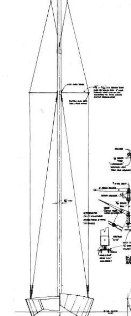
On a full size Star Boat the tall mast is supported by sliding back stays one one each side of the boat. The crew makes adjustments while underway, when the boat tacks the active back stay is released and the other back stay is pulled into position. The model star boat replaces the two back stays with a single back stay from a mast head fitting to a back stay fitting on the transom.
Radio control systems of any number of channels may be used but the functions are limited to
the rudder, sail control (jib sheets and main sheet) using no more than three servos. Control of the
jib may be separate or may be combined in one function.
Some skippers use a servo to control the back stay tension or they link to sail winch to slightly tighten the back stay when sailing down wind. With a jib boom that uses a swivel-vang the tension on the back stay changes as the jib moves.
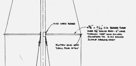
The mast head fitting maybe a "T" shaped fitting or as simple as a small tube of rod through a hole drilled in the msst head.
The main boom of a model is linked to the mast by a swivel connector which allows the boom to swing from side to side.
Typically the boom on a model needs to kept from lifting when the sails are not trimmed in hard.
To keep the main boom from flying up a "boom vang" kicker a simple device is set between the boom and the foot of the mast. Vangs take a variety of forms from a turnbuckle, to a piece of fishing line to a line controlled by a servo to allow the boom to be pulled down or allowed to raise up.
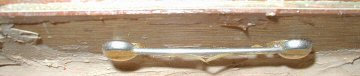
Often a left over length of extruded mast stock is used for a boom. Here is a gadget for connecting the sail tack to the boom end.
Originally on the old model the jib was loose footed and did not use a jib boom (aka a jib club). The addition of a jib club allowed the jib shape to be controlled.
Like the main sail the foot of the jib will fly up is some type of vang is not in place.
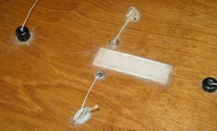
Typically a swivel is placed along the forward end of the jib boom and clipped to a deck fitting (aka jib rack).
The jib 1s a triangle. The halyard pulling the head of the jib places a force on the jib boom. The jib vang can be as simple as a swivel attached to the forward end of the jib boom and the jib-rack. As the swivel is moved forward and aft along the jib boom the leach of the sail has more or less ability to rise.

There are jib boom fittings ,( i.e. radial jib fitting), that anchor the jib stay and the forward end of the jib-boom to the bow. The radial filling attaches to the end of the boom with a gooseneck An rigid adjustable vang from the radial fitting to the jib boom control the lift of the boom at at set angle.
Some skippers also set up a forestay from the head of the mast to the radial fitting. This has the advantage of staying taught against the back stay as the sails are trimmed thus keeping the mast straight.
With a jib boom and swivel the pull against the back stay changes as the jib moves. Since the jib stay attached to the jib boom in this arrangement moves off center and is subject to varying wind forces the tension on the jib stay and back stay will vary.
The driving force of the sails is changed when the air slot between the mast and jib changes. Maximum driving force occurs when the curve of the jib luff is shaped to meet the curve of the main sail. Finding the best spot for the mast and jib swivel/radial fitting adds the challenge of setting up the sails prior to sailing.
Here is a bill for standing rigging fittings materials sent in by Forum members
photo's courtesy of "Larry Ludwig" at www.LudwigRCYachts.com, Ludwig Mfg.
- Gooseneck
- kicking strap
- Head fitting
- Turnbuckle
- Tangs
- cleats
- Bowsies
- single block
- Sheet Hooks
Of course there’s many things that can be substituted.
Instead of wooden or arrow shaft booms, airplane clips instead of the turnbuckles and so on.
- side stay racks and
jib rack
Quick release turnbuckles are nice.
- endclew.jpg
To:Star45@yahoogroups.com
From: 'J Fisher'jfisher@wildblue.net
Sender: Star45@yahoogroups.com
Date: Wed, 3 Jan 2007 21:02:38 -0700 (Mountain Standard Time)
Subject: Re: [Star45] Deck rigging and such.
Here is the list on the star 45 yahoo groups for rigging.:
GBMY item #, description, qty, purpose
- 019, 3/8' alloy tube, 1,
- Jib boom
- 034, Hales single block, 2, main and jib sheets
- 146, tapered drain plug, 1,
- plug in transom
-
182, Z sheet hook, 2, sheet ends/boom attachment
- 206, O-rings, 1, hold the Z hooks to the boom.
- 254, double block, 2, main sheet and jib sheet adjuster
- 255, sheet exit, 1, turning block for main sheet from under deck to above deck.
- 269, eye plate, 1, mounting for jib block.
- 272, 180 deg sheet lead, 1, turn around for jib tweaker
- 280, sheet hook, 1, hooks for backstay and fore stay.
- 282, tang, 1, attach lowers to mast.
- 907, rigging screw, 4 hooks, 2 packs, upper and lowers to the deck.
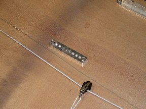
The chain plates that attach the shrouds (stays) to the hull take a lot of beatings. There is the load applied by the sails while under sail and there is the load as skippers pick up the model by the mast and carry it around.
Chain plates themselves can be as simple as a long screw eye bolt, as fancy as a jib-rack or tangs screwed into the side of a hull.
Which ever style of chain plate the hull and deck must be braced (reinforced) to withstand the loads.
Choose a material for stays that does not stretch. I have used solid stainless fishing leader. It works but it is not recommended. My preference is the stranded stainless wires used for U-control airplanes. If you can locate spools of stranded fishing leader/line it is a good choice. /p>
I bought a set of drills the sized to the diameter of the stays. I drill into the aluminum mast, push the wire out from inside the mast, swag a sleeve onto a doubled wire and pull the wire back and swag to the turnbuckle.
Models catch each other hooking onto stays. Sharp edges not only cut sails they also can stop models from un-hooking. Consider using short pieces if thin walled electrical tubing (shrink tube) which can be found in building supply places like Home D. or Lowes etc.
Sails for Star 45 Sailing Model
When buying or making your own sails remember the sail material is unrestricted. The key in sail materials is to select a light weight material. Cotton sail cloth is very much a obsolete material. Consider not only woven materials but also consider plastics such as mylar and mylar composites. Yes you can have colored sails made from ripstop nylon. There are a lot of colors available. Some modelers use colored markers to color sails. If you are making sails yourself for the first time choose a sail material that is low cost. As a do it your-selfer expect to botch the first few attempts.
You can make paneled sails, but it is not required. You can get PLENTY of use out of a single paneled sail. They actually have some advantages in high winds because of the less draught. Also, but putting in the luff curve and using a bolt-rope main, you do have a sail with some draught to it, not just a flat sheet of cloth. The block method works fine, but also.. is not required.
Basically you cut the bottom panel seam flat, and draw your airfoil MAC (mean aerodynamic chord) and cut it with a #9 X-acto or scissors. Use seamstress tape and over-stitch. Do the same thing with the luff curve, and hem the foot and leech and you are about there. Over-sew some corner panels, tack on some batten pockets and thread in a piece of weed-eater line up the hem of the luff and you are ready to put on your class markings and numbers. Grommets in the corners are installed either with a seamstress tool or they could be ordered from Don Ginther at GBMY if he is still shipping, he was in the process of suspending operations.
jfisher@wildblue.net has made a lot of saile using mylar bought from www.McMaster.com.
"Nylon ripstop is inexpensive. typically {estimated 207 prices} $6-$7 (x 38-50" long bolt) a yard at LONDON's Fabrics or HANCOCK Fabrics, sometimes you will find it at HOBBY LOBBY retail stores, but if you check your local fabric store you will most likely come up with some in various colors. Also using contrasting thread colors can make the sail more attractive. Start with a single panel sail and go through all the steps. When you are ready to start making paneled sails make them out of paper first. Typical brown paper can be cut and taped together and makes a perfect mock up of the sail for pennies."
Battens are allowed on the mainsail but are restricted to 4 in number, equally spaced along the leech and may not exceed 8.50 inches in length. Battens are not permitted in the jib sail {AMYA spec.}. Sails cut with a straight leech are OK provided there is no roach. If you have a roach with battens the roach must be cut to a smooth curve. If you buy a suit of sails order them to be made to the AMYA specifications for the S45 Class. The sails usually carry a 5 point "Star Emblem" at least 2 inches in size (measured from point to point across the flat of the star.
I recommend that sails include a bolt rope (i.e. a heavy piece of nylon line or even a heavy piece of solid nylon such as used in a weed trimmer).
"Al Stein" on Star45@yahoogroups.com contributed: "I think I got mine (sail material} from Potomac Sailmakers in Alexandria, Virginia... I bought yellow and orange, but they had a bunch of different colors in spinnaker cloth, and very light weight and airtight it is."
"It's fairly stiff, too, for as light as it is -- something well under an ounce per yard. Price about the same as Larry experienced... less than
$10 a running yard from a BIG WIDE bolt (can't remember exact width, but it was much wider than normal fabric store goods."
"John Kelly" on Star45@yahoogroups.com
"I have built US One Meter sails from spinnaker cloth purchased from Sailrite.I used .5 oz which is only available in red, white, and blue, but .75 oz is available in a multitude of colors. The part I like best about these materials is you can buy a role of C3 spinnaker tape (pricey at $25.00) and build a set of sails without sewing a stitch. They actually use C3 to tape together the body seams of full scale spinnakers so I'm pretty sure it can take just about anything a model can throw at it. I've built two sets of sails and only used about 10% of my role of tape so that $25.00 will go a long way."
At about $12.00 a yard, spinnaker cloth is twice the cost of fabric store ripstop, but spinnaker cloth is coated with resin that makes it far more stable and eliminates all porosity (wind can blow right through ripstop).
For cutting fabric like this he uses a hot knife. He bought a $4.00 40watt soldering iron at the local mega-mart, removed the tip, hammered it flat, and put it back in. Cutting works best over a smooth heat resistant surface."
Visit Rod Carr, Maker of Model Yacht Sails with 37 Years Experience making sails and helping fellow skippers.Carr Sails FAQ
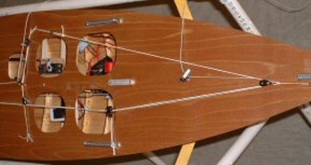
Before attaching a deck design the hatches and bracing required. It has been my experience that skippers grab the model hatch rim and lift the model to carry the model to to pick it up from the water. (sure, there are others that don't do this:)
Install all your servos, sail winches, keel, rudder, radio equipment, and batteries. Design your hatch sizes and locations to permit your hand(s) to access and remove these items.
Universal Model SailboatStand
Keeping it simple:
Legs and cross pieces 1 x 2 pine (or similar wood)
Straps are nylon chair variety, substitute nice looking heavy nylon rope.
Paint, or stain and varnish
Nice brass name plate on cross brace
Dropping a model into the stand can cause the stand to close up and pinch the model if the keel doesn't sit on the ground. I mount the stand on a piece of plywood so the legs don't hit the model. Or add rope cross ties at bottom of legs and you can fold the stand for carrying.
IMHO, it is good practice to have models sit on their keels and have the weight of the model supported by the keel. Plastic models (i.e. thin skinned epoxy-glass) have been known to deform when hung from a stand.
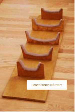
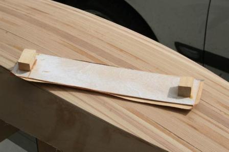
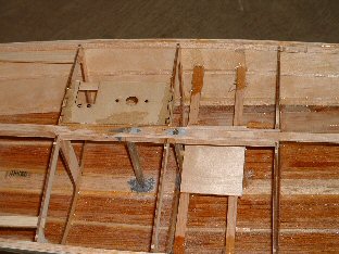
Phil Geren needed a cradle for a woodie Star 45 hull under construction to hold the hull while fairing the gunnels to the frames in preparation for installation of the deck and while designing and installing the controls.
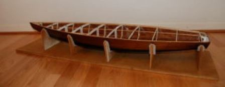
A easy way to make a perfect cradle is by using the holes (which are left in the John Fisher lasercut frame sheets) after removal of the lasercut frames, to trace the exact shapes of the outsides of frames 2, 4, 6, 8, and 10 onto 3/8' thick plywood. Allow for the thickness of planking and carpeting by drawing a second trace for each frame so that the hole for the hull is 3/8' bigger everywhere than the frame. Then cut out each second trace as the inside of a frame for a cradle. Mount the cradle frames on a 2'X4' piece of particle board, using the spacing of the balsa template included in the frames kit, and using a try square to get them vertical, and making sure that they are all on the same longitudinal center and all parallel. Then hot glue 1' wide strips of carpeting to the insides of the cradle frames. Voila! A perfect hull cradle.
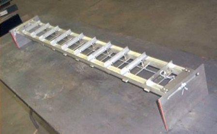
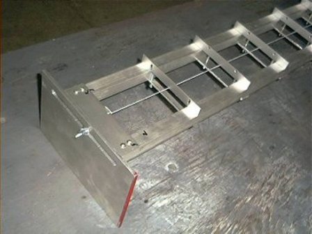
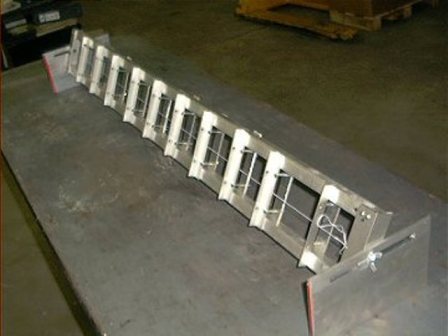
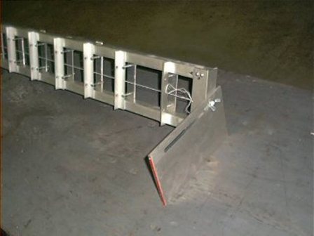
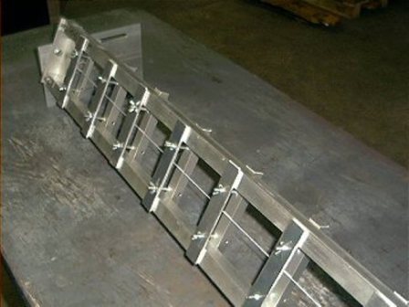
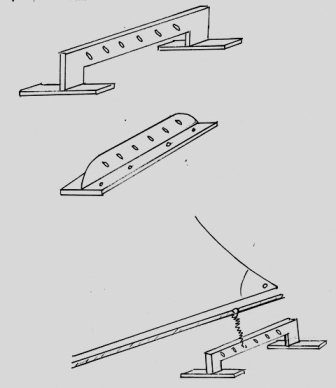
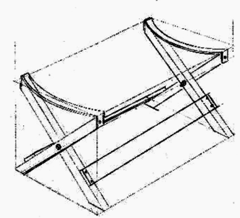
Michael Duddy built an elaborate metal building jig. Duddy's jig allows the builder to re-position the hull as it is being built and can be used to hold frames of different models.
Thu, 21 Dec 2006 08:28:46 -0500
The material used in the jig is 1"x1"x1/16" aluminum square tube( very ridged and no twist).
The ends are 1 1/2" angle bolted in two places on the ends as you can see in the pictures. Check the ends with levels assure the jig is dead straight.
The angle pieces with the screws in them are 3/4"x 1/16" x 6" long. You mount your frames to these with a square on the centerline of your frame inline with the center of the attachment piece.
Next you use a square to square these on the jig rails, and line up with the string. Now you are rite on brother.:) The dimensions of this jig are ; 60" long x 6" wide because they only had 60" pieces in the rack , and you know what you might be building in the future. You can make it any size you want.
The end plates I made from 1/4"(stuff laying around), and milled slots in them so I could slide the jig to one side or the other for balance. If you have any questions or if I can help you in any way , get in touch with Mike mikes025 at comcast.net.
|